
On Clear Parts the Joint Is Visible: Whitening, Haze and Witness Marks
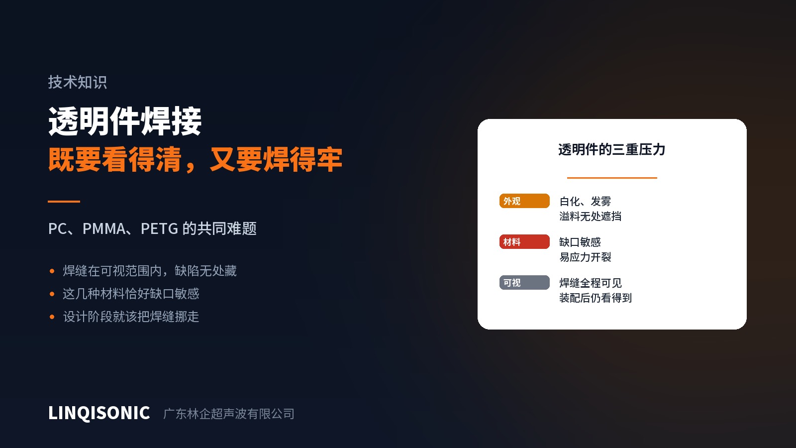
On an opaque part the joint hides inside the housing and nobody looks as long as it is strong. On a transparent part the joint, the melt flow marks and the horn's witness mark are all in view, and the criterion shifts from strong enough to good enough to look at.
Whitening is scattering, not discolouration
The whitening seen on PC and PMMA is usually not the material changing colour. Large numbers of micron-scale crazes form inside the material and scatter light at their internal surfaces, which reads as white haze. Crazing needs tensile stress, and the welding process supplies it: horn pressure at the edge, transverse ultrasonic motion, shrinkage on solidification, and fixture constraint.
So every remedy points at reducing local stress.
Lower the weld force. Force on PC is often set too high and the edges whiten immediately.
Raise amplitude and shorten time. Reaching melt quickly beats grinding away at low amplitude, because it shortens the time stress is applied.
Increase the horn contact area. A small contact area means high pressure, and high pressure means high local stress.
Do not force the part straight in the fixture. A part welded in an unnatural shape whitens near the constraint points.
One more that gets missed: PMMA and PC both absorb moisture, but our route is joint design and parameters rather than pre-treatment. A shear joint keeps the melt sealed between the mating faces, and combined with amplitude and force adjustment it is more controllable than working on the incoming material.
Haze is a record of melt flow
Light haze near the joint is usually the trace left by melt flowing through it. Along the path the melt took, orientation and cooling rate differ from the bulk, so the optical properties differ too.
The fix is structural. Moving the joint out of the visible area is the complete answer. Where that is impossible, use a shear joint to confine the melt between the mating faces so it never spreads onto a visible surface; add a flash trap to catch what does escape; and reduce energy to just enough fusion, since surplus energy becomes surplus melt.
Witness marks are the horn face copied over
Under force and vibration, plastic copies the horn's surface texture exactly. Machining marks, wear pits and stuck material on the horn all print onto the part.
Three directions.
Polish the contact face. Horns for transparent cosmetic parts need a surface finish a grade better than usual, worked to mirror level.
Add an interlayer. A thin film or soft pad between horn and part reduces marking substantially, at the cost of periodic replacement and some energy loss.
Change the horn material. Titanium has better surface hardness and wear behaviour than aluminium, so its face stays stable over long runs and does not print a changing mark as it wears.
And material pick-up: melt stuck to the horn prints onto the next part. Pick-up usually comes from excessive amplitude, low force or a naturally tacky material, so besides cleaning, look back at the parameters for the cause.
Judging it on the line
The difficulty with cosmetic parts is that the criterion is hard to quantify. What works is a set of limit samples — acceptable, borderline and rejected — judged under fixed lighting and viewing angle, backed by process data, since drift in post-weld height and energy usually precedes the cosmetic problem.
Fixing the judging conditions is far more productive than arguing repeatedly over whether something counts as white.
Process notes for PC and PMMA are in the material handbooks on the downloads page. Horn face preparation, amplitude and force control are on the ultrasonic welding machine pages.
Send drawings, the visible area and the cosmetic standard to 1427498429@qq.com, or call +86 769 8202 9510 / +86 137 6001 0932.