
Welding Carbon-Fibre Composites and the Horn That Pays for It
Carbon-reinforced PA, PPS and PEEK appear more and more in aerospace, medical and semiconductor equipment parts. The welding difficulty shares its cause with glass fibre, but three things belong to carbon alone.
The shared part first
Fibre takes no part in fusion, so less resin is available at the interface; fibre and resin differ in acoustic impedance, so energy is lost at every interface the wave crosses. The higher the loading and the longer the path, the less amplitude reaches the joint.
The typical symptom is a surface already marked and polished while the interface is still unfused. Extending the weld time here works backwards and only deepens the surface damage. The right direction is more amplitude first, and above a certain loading a change of joint form from energy director to shear joint.
Three things specific to carbon
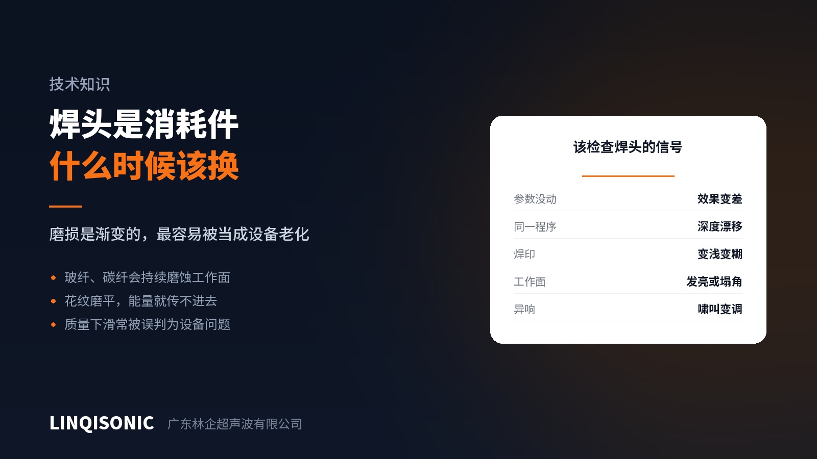
One: the horn wears much faster. Carbon is harder than glass and more aggressive toward the working face. Aluminium horns have short lives on carbon-filled material, and titanium with surface hardening is the usual answer.
More important is managing the horn as a consumable: set the replacement interval by piece count, photograph the working face on a schedule and compare, and carry spares in the plan. Wear is gradual, and by the time yield drifts a batch has already passed.
Two: carbon fibre conducts. This one is easily overlooked. Carbon dust is conductive, and finding its way into a control cabinet, a connector or a sensor it causes shorts and spurious operation.
Fit local extraction at the station, seal the control cabinet properly, and clean on a schedule. Unlike the chemical attack from PVC, this is an electrical risk, but the answer is the same extraction.
Three: dust protection. Carbon dust irritates the airway, so station extraction and operator protection should follow the plant's occupational health requirements.
Joint design
Prefer a shear joint. On heavily filled parts the tip of an energy director may itself be a fibre-occupied section that will not melt. A shear joint fuses progressively along the mating face and is far more stable.
Design to the filled strength. Fibre is interrupted across the interface and joint strength cannot reach parent-material level. Design that section for lower stress or lengthen the joint rather than expecting parameters to compensate.
Design for near field. Carbon attenuates strongly, so the horn should contact as close to the joint as possible — a drawing-stage decision.
On aerospace parts
Welding the material and qualifying an aerospace part are two different things. Joining processes for aerospace components normally go through the OEM's or tier-one supplier's own process qualification: coupon testing, destructive examination, batch consistency verification and special-process audit, and that process is led by the customer.
What an equipment supplier provides is a repeatable result with complete process records: limits and alarms across time, energy, power, absolute depth, relative depth and force, the weld curve displayed in real time, and parameters stored and exported into the customer's own traceability system. We do not perform non-destructive testing, and we do not undertake qualification of aerospace parts.
Difficulty ratings and joint dimensions are on the downloads page. Amplitude ranges, horn selection and process monitoring are on the ultrasonic welding machine pages.
Send the grade, fibre content and drawings to 1427498429@qq.com, or call +86 769 8202 9510 / +86 137 6001 0932.