
Welding PP: Strong Joints Without Marking the Surface
With PP (polypropylene) parts, customers usually state two halves of the same requirement: the joint must be strong, and the surface must not be marked.
On PP those two are harder to satisfy together than on most materials, because they pull in opposite directions. Strength needs energy delivered to the interface; and once the energy rises, the relatively soft PP surface takes an impression from the horn.
The answer is not to compromise between them. It is to change the approach: do not increase total energy — arrange for less of it to pass through the surface and more of it to stay at the interface.
Start with what PP is
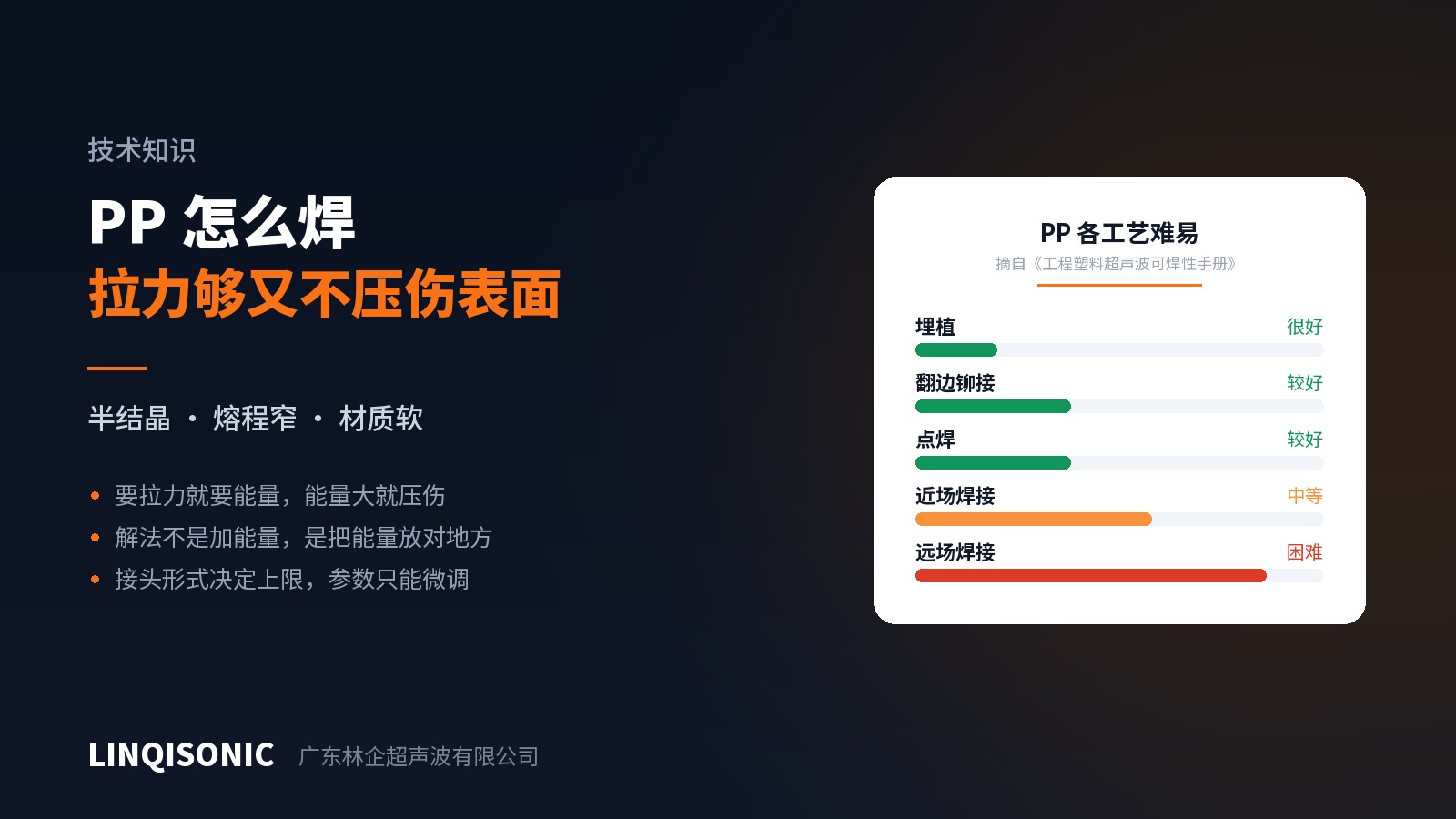
In our Weldability of Engineering Plastics handbook, PP's ratings are widely spread: very good for insertion, good for staking and spot welding, moderate for near-field welding and difficult for far field.
That spread is itself the explanation. PP is semi-crystalline, with a defined melting point and a narrow melting range; it also has high internal damping and low stiffness, so the acoustic wave attenuates quickly within it. Wherever the horn can press close to the joint — insertion, staking, spot welding, near-field welding — things go well. As soon as vibration has to travel through the body of the part to a distant joint, very little of it arrives.
First conclusion: design PP parts for near field, and avoid far field wherever possible. That decision is made on the drawing and cannot be recovered later.
Where the strength comes from
Joint form sets the ceiling; parameters only fine-tune.
For semi-crystalline materials a shear joint generally beats an energy director. An energy director relies on instantaneous melting at a tip followed by flow, and with PP's narrow melting range that instant is hard to reproduce — within one batch some parts fuse fully and others fall short. A shear joint generates heat through sustained friction along an interference fit, so melting advances progressively along the mating face; the process is far more controllable and the weld area larger.
Weld depth matters more than force. Strength comes from the area actually fused, not from how hard the parts are pressed together. Force exists to keep the faces in contact and consolidate the melt; too much of it squeezes melt out of the joint while marking the surface. This is where a lot of machine setting goes in the wrong direction.
The fixture has to support the part. PP has low stiffness and deflects under weld force. If the fixture supports only the edges, the centre sinks, the actual pressure varies along the joint, and the result is a weld that is sound in places and starved in others. The support area must be generous and follow the part contour.
Protecting the surface
1. Increase the horn contact area. At the same force, doubling the contact area halves the pressure. The horn's working face should follow the contact region of the part rather than bearing on a small patch.
2. Put the contact point on a non-cosmetic face. Again a design-stage decision. Most PP parts have a visible side and a hidden one; place the horn contact where it will not be seen after assembly and the problem disappears.
3. Control approach speed and trigger method. Much of the impression comes from the horn arriving quickly against the surface. Reducing approach speed and triggering on position or force rather than on contact makes a visible difference.
4. Consider a higher frequency where appropriate. Higher frequency means lower amplitude for the same energy, which is gentler on thin walls and cosmetic faces; the trade-off is lower available power and a smaller maximum weld area. It suits small, thin, appearance-critical parts — larger parts still call for a lower frequency.
5. Watch the condition of the horn face. Roughness or damage on the working face transfers one-to-one onto PP. This shows up more on soft materials than on rigid ones and warrants regular inspection.
Putting it together
Back to the original conflict. When strength and appearance collide, work in this order:
Confirm whether the design is near field — if it is far field, fix that first; everything else is wasted effort.
Review the joint form — replacing an energy director with a shear joint often improves strength and appearance at the same time, because fusion is more complete and less total energy is needed.
Then horn contact area and trigger method — these two govern marking directly.
Only then adjust parameters. Parameters fine-tune a sound design; they do not rescue a poor one.
Working the other way round — exhausting the parameter space first, then blaming the material — is the most common and most time-consuming path.
Where the full reference sits
This article covers the reasoning for PP. The Weldability of Engineering Plastics handbook gives complete difficulty ratings for common engineering thermoplastics across near-field welding, far-field welding, staking, insertion and spot welding, together with a dissimilar-material compatibility reference. The Energy Director & Joint Design Guide gives the full dimensional system for eight joint types, including how shear-joint interference is banded by part size. Both are available from the downloads page.
PP parts are usually designed for near field, with specific demands on stroke, force control and trigger method. Model configurations are on the ultrasonic welding machine pages.
To have a PP part assessed, send drawings or a sample to 1427498429@qq.com, or call +86 769 8202 9510 / +86 137 6001 0932.