
Ultrasonic Welding of PEEK: Difficulties and Solutions
PEEK (polyether ether ketone) is increasingly used in aerospace, medical and semiconductor equipment, which raises the question of whether it can be joined by ultrasonic welding.
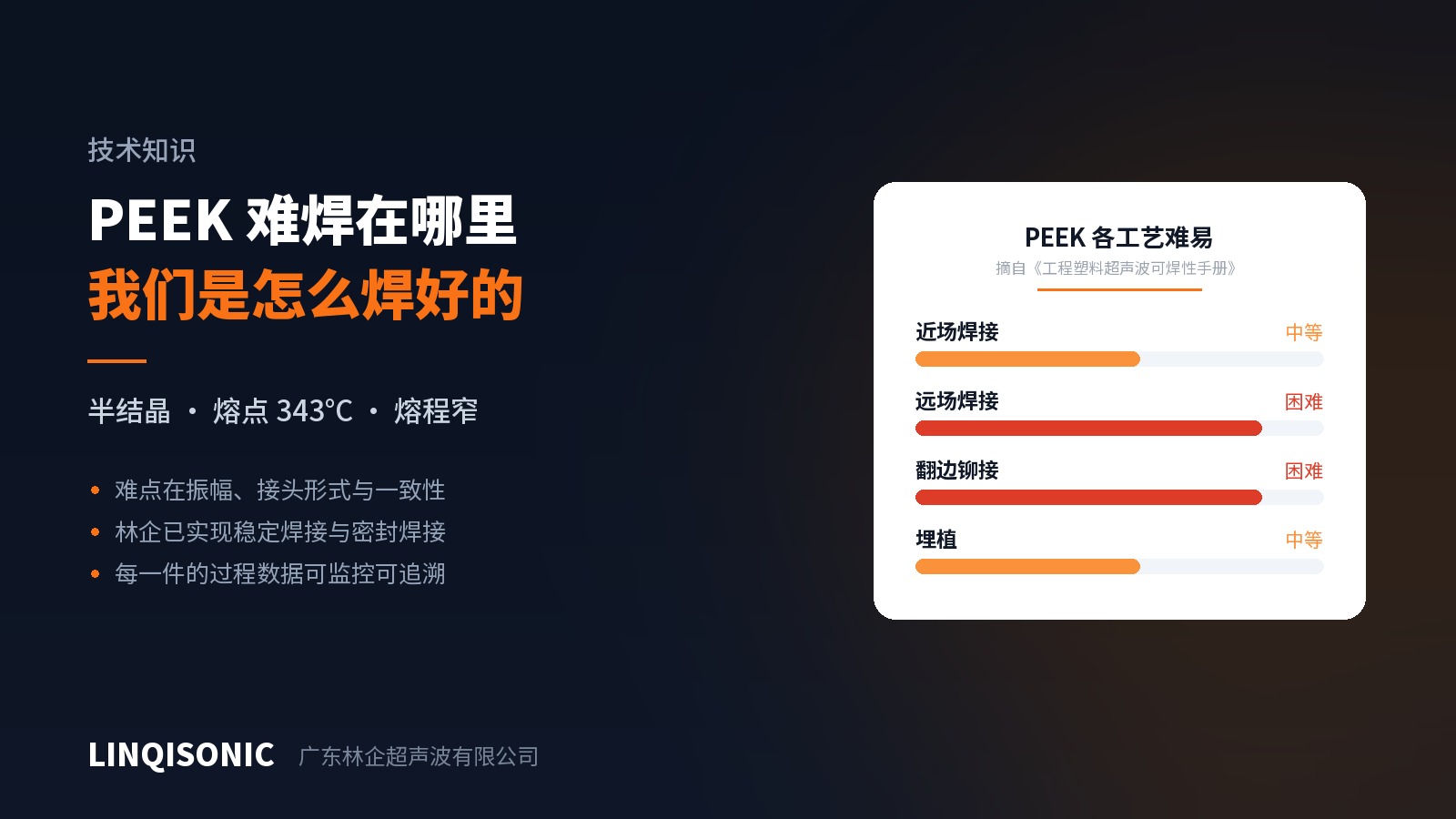
It can, and we already do. But it is worth being clear about where the difficulty lies. In our Weldability of Engineering Plastics handbook, PEEK does not rate well: moderate for near-field welding, difficult for far-field welding, difficult for staking, moderate for insertion. That rating is not conservatism — it follows from the material.
Where the difficulty lies
It is semi-crystalline, with a high melting point and a narrow melting range.
PEEK has a glass transition temperature of roughly 143°C and melts at about 343°C. Semi-crystalline materials lack the broad softening region of amorphous resins: below the melting point the material is solid, above it the material flows quickly, and the usable window in between is narrow. Energy input therefore has to be both fast and precise. Too slow and the heat dissipates into the surrounding material before the interface melts; too fast and the resin near the joint overshoots and degrades.
Melting it takes more energy in the first place.
A semi-crystalline structure absorbs additional heat to break down its crystalline order. For the same joint geometry, PEEK requires a noticeably higher energy density than amorphous resins such as ABS or PC, and correspondingly more amplitude.
Far-field welding is particularly difficult.
In far-field welding the horn contacts the part some distance from the joint, so vibration must travel through the body of the part to reach the interface. The ordered molecular structure of semi-crystalline resins attenuates the acoustic wave more strongly, and what arrives at the joint is often insufficient. That is why PEEK rates as difficult in far field — not impossible, but with poor repeatability and a narrow window.
Fibre reinforcement raises the difficulty again
Aerospace parts generally use carbon- or glass-reinforced PEEK, and the fibre works against the process in two ways at once: it attenuates the acoustic wave, and it reduces the amount of resin available to fuse at the interface.
This is the same mechanism discussed in our previous article on glass-filled plastics, here superimposed on a substrate that is already hard to weld. Carbon-filled PEEK deserves particular attention: carbon fibre is harder than glass and more aggressive toward the horn's working face.
What can be done
1. Design for near field. The closer the horn contacts the part to the joint, the better. Where the horn can reach the part should be planned at the design stage rather than worked around after the geometry is fixed. The gap between near and far field is far wider on PEEK than on amorphous resins.
2. Treat amplitude as the first variable. PEEK needs more amplitude than common engineering plastics. Where amplitude is insufficient, extending the weld time only spreads heat into the surrounding material while the interface stays unfused — the same trap described in the glass-fibre article, and more pronounced here.
3. Prefer a shear joint. For semi-crystalline materials, a shear joint generating heat through sustained friction along an interference fit is usually more stable than an energy director relying on instantaneous melting at a tip. This is especially true at higher fibre loadings.
4. Make the fixture rigid. A narrow energy window demands high repeatability. If the part can move within the fixture, the energy path differs from piece to piece and results drift.
5. Treat the horn as a consumable. Fibre-reinforced PEEK abrades the horn's working face; inspect it on a schedule and carry it in the spares plan.
Difficult, but workable
All of the above describes difficulty, not impossibility. We weld PEEK parts reliably in production, including applications with sealing requirements.
Mapped against the difficulties above, three things make that possible.
First, sufficient amplitude, delivered accurately. PEEK needs more amplitude than common engineering plastics, and the machine's amplitude range and resolution determine whether there is headroom at all. Where amplitude falls short, no adjustment of time or force will recover it — as noted above.
Second, the right joint form, chosen at the design stage. On semi-crystalline materials a shear joint is more stable than an energy director, and whether the horn can reach close to the joint — near field versus far field — matters more on PEEK than on most resins. This work happens on the drawing, not at the machine, which is why we prefer to be involved before the tool is cut.
Third, consistency comes from process monitoring, not from feel. A narrow energy window means that "this part welded well" and "every part welds well" are different statements. That is especially true for seals: too little weld depth leaks, too much causes flash or cracking. The equipment allows upper and lower limits to be set across time, energy, power, absolute depth, relative depth and pressure with alarms on deviation, displays the weld curve in real time, and stores the process record for each part. Materials with narrow windows are precisely the ones that need this.
In other words, welding PEEK well is not a matter of some proprietary parameter set. It is a matter of having amplitude headroom, the right joint design, and process consistency — all three. Miss any one and it shows up in volume production.
On aerospace parts, to be clear
Welding the material and qualifying an aerospace part are two different things.
Joining processes for aerospace components normally go through the OEM's or tier-one supplier's own process qualification: coupon testing, destructive examination, batch consistency verification and special-process audit requirements. That process is led by the customer. An equipment supplier provides machines that reproduce a result consistently, along with complete process records — it cannot carry out the qualification on the customer's behalf.
On that point we state only what we provide. On the equipment side, monitoring limits can be set across time, energy, power, absolute depth, relative depth and pressure with alarms on deviation; the weld curve is displayed in real time; and parameters can be stored and exported so that process data can be folded into the customer's own traceability system.
We do not perform non-destructive testing, and we do not undertake qualification of aerospace parts. That work sits with the customer.
Conclusion
PEEK sits at the harder end of the range, but that difficulty can be covered by process knowledge and machine capability — provided it is acknowledged rather than papered over with experience from easier materials.
One caution: treat any offer of "general PEEK welding parameters" with suspicion. The real values depend on part geometry, fibre content, joint form and fixture condition, and have to be established by trial. That is how we do it ourselves — trial first, then fix the parameters, then lock them in with process monitoring.
The Weldability of Engineering Plastics handbook rates common thermoplastics, PEEK included, across five processes and includes a dissimilar-material compatibility reference; the Amplitude Reference Guide covers amplitude requirements by material family; the Energy Director & Joint Design Guide gives the full dimensional system for eight joint types. All are available from the downloads page.
PEEK demands more amplitude headroom and tighter process monitoring than common engineering plastics; model capabilities are on the ultrasonic welding machine pages.
To have a PEEK part assessed, send drawings or a sample to 1427498429@qq.com, or call +86 769 8202 9510 / +86 137 6001 0932.