
Why Glass-Filled Plastics Fail in Ultrasonic Welding
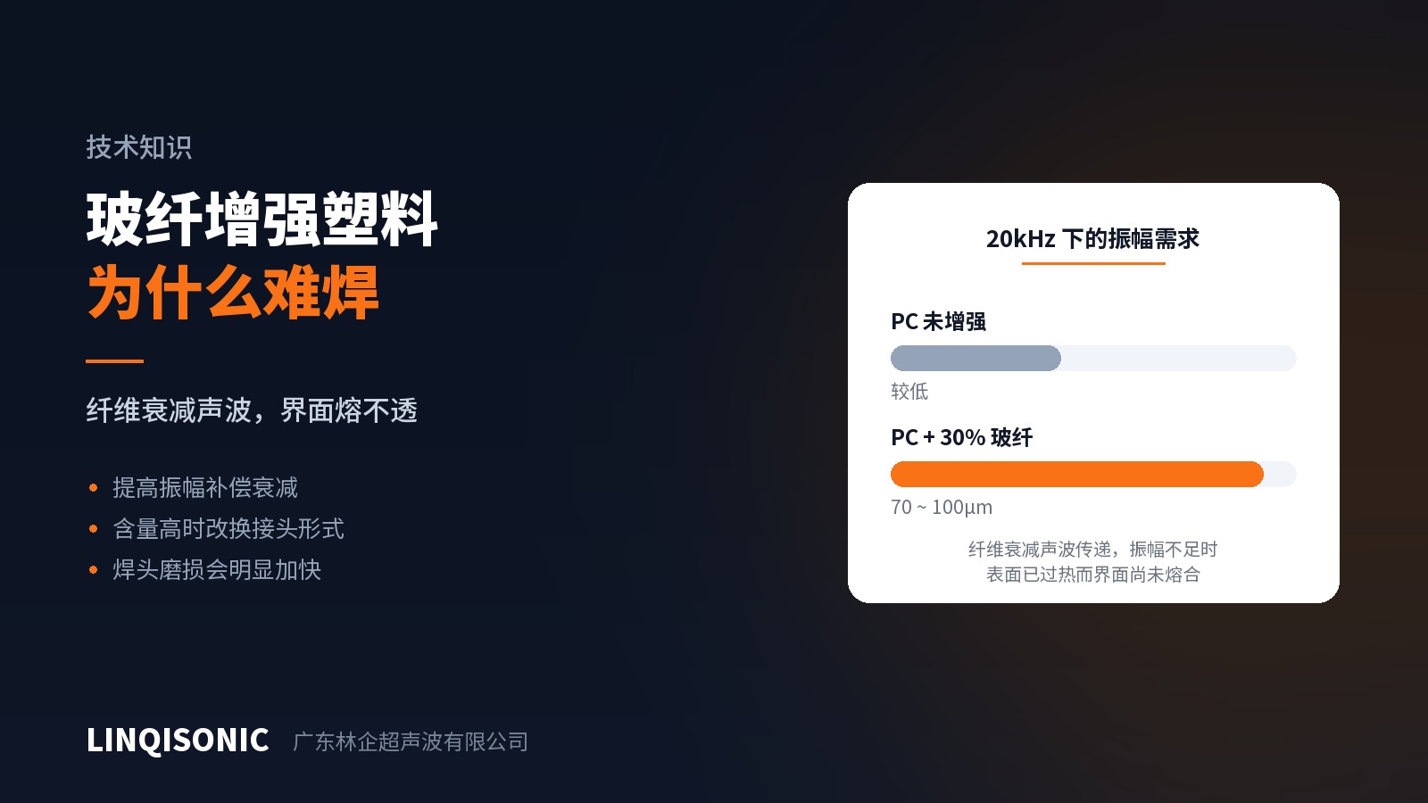
Glass-filled grades come up more often than any other material in ultrasonic welding enquiries, and they are also the most likely to cause trouble. The symptoms take two forms: the joint is weak and separates under load, or the surface is already scorched and marked while the interface still has not fused.
Both come from the same cause.
The fibre interferes at two points
First, glass fibre attenuates the acoustic wave.
Ultrasonic welding depends on vibration travelling from the horn into the part and on to the joint interface. Resin and glass fibre have different acoustic impedances, and energy is lost at every interface the wave crosses. The higher the fibre content and the longer the path, the less amplitude survives to reach the weld.
That explains the scorched surface with an unfused interface: energy density is highest near the horn contact face, while the interface is where energy is scarcest. Seeing a weak joint, an operator extends the weld time and increases the force — which only deepens the surface damage while the interface remains unmelted.
Second, there is simply less weldable resin at the interface.
Only the resin forms the weld; the fibre takes no part in fusion. In a 30% filled grade, roughly a third less material at the interface is available to melt, and the fibre also forms a mechanical barrier across the joint face. Even with full fusion, joint strength cannot reach that of the base material — something to account for at the design stage rather than hope to recover through parameter tuning.
What to do, in order
First, raise the amplitude — not the time.
Amplitude governs the energy density delivered to the interface per unit time; extending the cycle merely gives heat longer to spread toward the surface. For PC with 30% glass fibre, 70–100μm at 20kHz is the suggested range, noticeably above the usual figure for the unfilled grade.
There are three routes to more amplitude: a higher-gain horn, a different booster ratio, or a generator with a wider amplitude adjustment range. Which is available depends on the existing equipment.
Second, above a certain fibre content, change the joint form.
This step is often skipped. An energy director relies on a sharp tip to concentrate energy, melt quickly and flow out; high fibre content weakens both the melting and the flow. Beyond a certain loading no amount of amplitude will produce a consistent weld, and the answer is a shear joint — which forms the weld through sustained friction along an interference fit on the side wall, and is markedly less sensitive to fibre.
The loading at which that switch becomes necessary, and the height correction for energy directors at different fibre contents, are set out in the Weldability of Engineering Plastics handbook.
Third, budget for horn wear.
Glass fibre is far harder than resin and abrades the horn's working face during welding. Above about 10% fibre content, wear accelerates noticeably and the service life of a titanium horn is materially shortened. In volume production of filled parts the horn is a consumable: inspect the working face on a schedule and carry it in the spares plan, rather than discovering the cause only after weld quality has drifted.
Common misconceptions
"If it is weak, weld it longer." As above, this pushes the problem toward surface damage. The process window for filled parts is usually narrower than for unfilled grades, not wider.
"Same grade, so a new batch is fine." Fibre content, length distribution and sizing chemistry can all vary between batches, and filled parts are more sensitive to that variation. Re-confirm parameters after a batch change.
"Filled parts weld badly because the machine lacks power." Power determines how much energy is available; amplitude determines the density at which it enters the interface. What filled parts usually lack is the latter, and increasing power will not compensate for insufficient amplitude.
Most of it is decided on the drawing
Weld quality on filled parts is largely determined before any machine is involved: whether the joint form suits the material, whether wall thickness supports the required interference, and whether the energy director is positioned so that energy reaches the interface. Once the tool is cut, the room to adjust is small.
The Weldability of Engineering Plastics handbook rates common thermoplastics across five processes and explains the influence of glass fibre, flame retardants, pigments and regrind; the Amplitude Reference Guide covers amplitude requirements by material family; and the Energy Director & Joint Design Guide gives the full dimensional system for eight joint types. All are available from the downloads page.
Available amplitude depends on the generator and acoustic stack. Adjustment ranges by model are listed on the ultrasonic welding machine pages.
To have a specific part assessed, send drawings or a sample to 1427498429@qq.com, or call +86 769 8202 9510 / +86 137 6001 0932. The online technical consultant on the website can also take questions directly.