
How Far From the Weld Should an Insert Sit
A threaded insert sits in the housing with the weld line beside it, and after welding the insert is loose or the plastic around it has cracked. Both come down to distance.
An insert changes three things
Stiffness. Metal has a modulus two orders above plastic, so the insert region barely deflects. Under weld force the flexible regions sink first while the insert section holds up, and pressure along the joint becomes uneven.
The acoustic path. Metal and plastic differ greatly in acoustic impedance, so the interface reflects and scatters. The insert can divert vibration or act as a reflector, making the energy distribution nearby hard to predict.
Heat. Metal conducts far better than plastic, so the insert acts as a heat sink. The section of joint near it loses heat continuously, and the same energy does not melt it to the same degree.
The risk runs the other way too
The welding vibration also acts on the insert. An insert is held by molten plastic that flowed into its knurl and undercuts and then solidified. If the plastic nearby is repeatedly heated near its softening point during welding, that lock loosens.
Typically pull-out strength passes before welding and drops after. Inspecting only after the insertion operation misses this entirely.
Setting the distance
There is no universal figure, because it depends on wall thickness, material, insert size and weld energy. What is usable:
Keep the insert outside the heat-affected region. Section a welded part and see how far the fused band and the discoloured zone reach; the insert should sit beyond that.
Keep the wall uniform around it. If the boss carrying the insert runs straight into the wall that carries the joint, the stiffness step reaches the joint. Leave a section of uniform wall between them.
Do not put the insert directly behind the joint. The same reasoning as a rib: a stiffness step directly behind has the greatest effect.
When it cannot be avoided
Support the section in the fixture so both stiff and flexible regions are backed up and pressure evens out.
Use energy or relative depth mode so the machine adapts to the real condition instead of running a fixed time.
Change the sequence. Where the structure allows, weld first and insert afterwards so the two operations do not interfere. It is often overlooked and often the cleanest answer.
Move the test. Run pull-out and torque checks after welding rather than after insertion.
Insertion basics
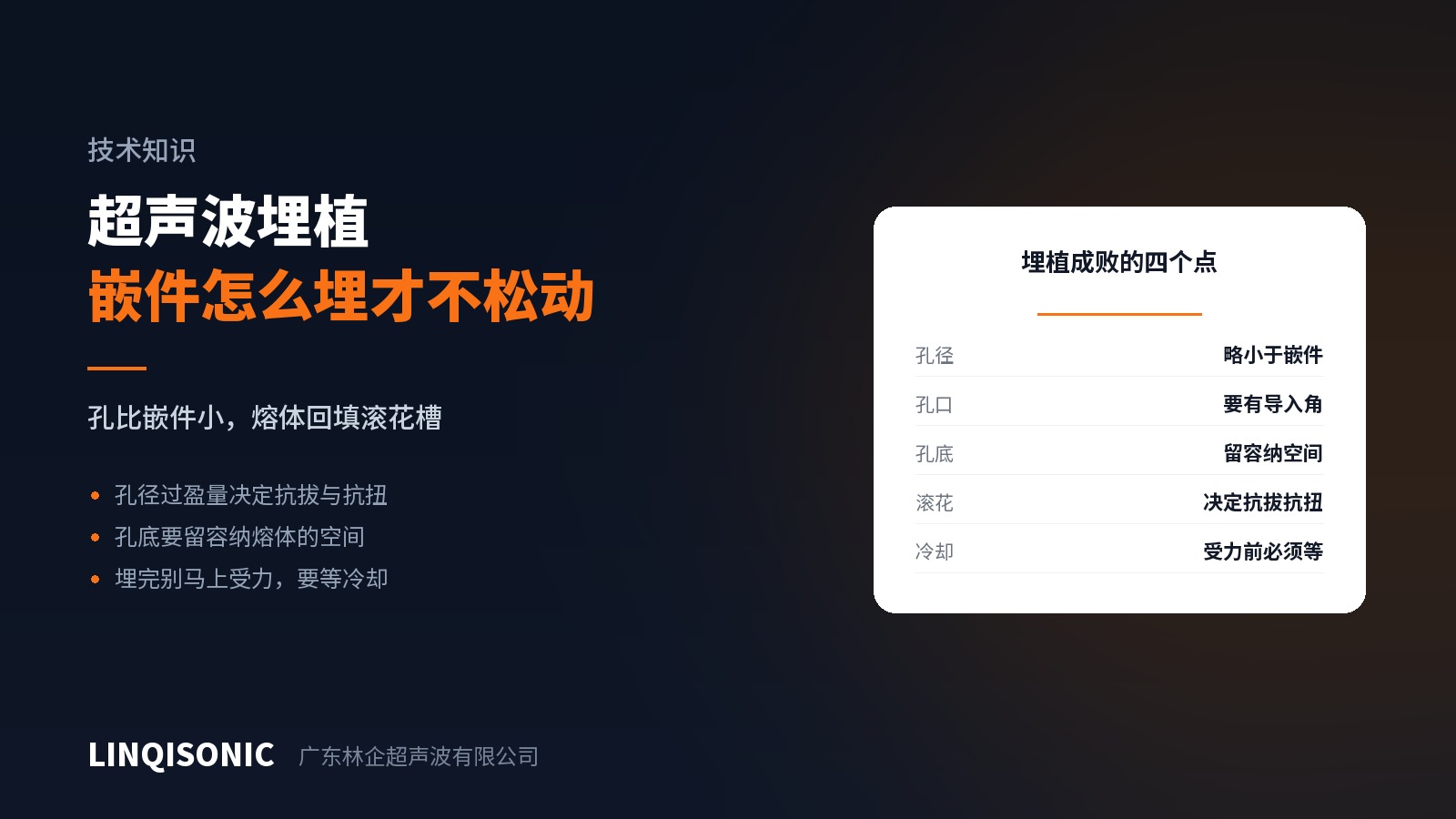
The bore is slightly smaller than the insert: too little interference and melt cannot fill the knurl, too much and material is displaced to the bore mouth or splits the boss. Put a lead-in at the mouth, leave volume at the bottom to receive displaced melt, and choose the knurl by the load — circumferential resists pull-out, axial resists torque.
Bore diameter and depth values and interference bands by material are in the handbooks on the downloads page. Depth modes and insertion tooling are on the ultrasonic welding machine pages.
Send the insert specification, wall thickness and joint position to 1427498429@qq.com, or call +86 769 8202 9510 / +86 137 6001 0932.