
Lamps and Sealed Parts: Leak-Tight Is Not the Same as Strong
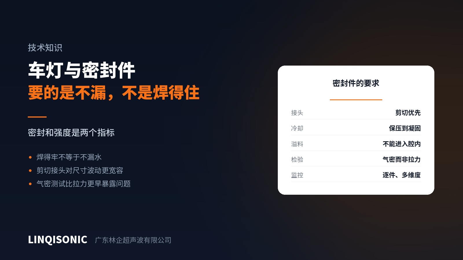
Lamps, sensor housings, pump bodies, waterproof connectors — these parts are judged on one criterion: they must not leak.
Strong and leak-tight are different measures. One continuous microscopic path through the joint is enough for a part that passes every pull test to leak.
Sealing fails at the shortest link
Structural welding is judged on the total strength of the joint, where a locally weak section is made up elsewhere. Sealing is judged on the weakest point, and one discontinuity scraps the part.
Sealed parts therefore demand far more consistency along the joint than structural parts: seating, energy distribution and cooling must all be uniform around the whole perimeter.
Prefer a shear joint
With an energy director, melt is squeezed outward, and where melt volume varies, local discontinuity can follow.
A shear joint behaves differently: the side walls engage with interference, melt stays confined between the mating faces, and a continuous bond forms around the full perimeter. The interference fit also provides a layer of mechanical sealing in its own right, so a slight shortfall in fusion still has a second line of defence.
Shear joints are the first choice for sealed parts, round and rectangular housings alike.
Parameter direction
Hold must be adequate. The most frequently overlooked point on sealed parts. Melt solidifying under force shrinks evenly; release force early and shrinkage leaves microscopic channels in the joint — possibly too small to see in section, but never small enough to pass a leak test.
Do not over-force. Excessive force thins the melt to the point of discontinuity.
Use energy or distance mode. Time mode cannot compensate for incoming variation, and sealed parts cannot absorb it.
Control the direction of flash. Flash entering the cavity affects light transmission in optical parts and performance in sensors. Fix flash trap position at the design stage.
Inspection
Leak test every part, not a sample. Seal failures are randomly distributed and sampling will miss them.
Test under conditions that match service. Lamps face thermal cycling, vibration and damp heat; passing a room-temperature test at despatch does not mean the part stays sealed on the vehicle. Retest after thermal cycling where possible.
Correlate process data with leak results. Recording energy, power and post-weld depth for every part and comparing against leak results shows which dimension is most sensitive to leakage, and the monitoring limits can then be tightened on that dimension.
Design considerations
Give the joint flange enough stiffness. A soft flange deflects during welding and seating varies around the joint.
Avoid running the joint across abrupt wall transitions. Shrinkage conditions differ there, making them frequent leak sites.
Radius the corners generously. Melt flows poorly into sharp corners and discontinuities form, which is why rectangular housings are harder than round ones.
Keep lens and body materials compatible. A PMMA lens on an ABS body is a common and compatible pairing; PC on ABS has a narrower window. Where materials are incompatible, no parameter set produces more than contact, and the part will leak in service.
Hold control and per-part monitoring are described on the ultrasonic welding machine pages. Joint design and material compatibility are covered in the handbooks on the downloads page. Send drawings, material combination and leak requirements to 1427498429@qq.com, or call +86 769 8202 9510 / +86 137 6001 0932.