
Choosing a Leak Test Method and Setting the Criterion
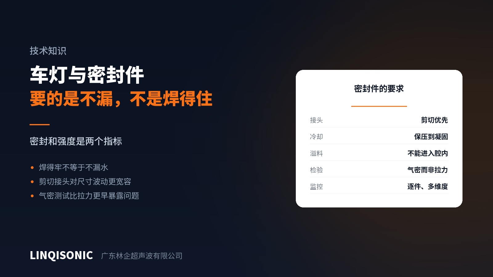
"This part has to be airtight" — followed by dunking it in water and watching for bubbles. It is the most common approach and the one most likely to give the wrong answer.
Work out the criterion first
Leak rate is usually expressed in Pa·m³/s, and also in sccm or mbar·L/s. The units convert; what matters is establishing how much the product may leak.
That figure comes from the application: the cavity volume, how much pressure change is acceptable over what period, whether the medium is gas or liquid, and the operating temperature range. As an illustration, a sealed cavity that must not gain significant humidity over three years tolerates a leak rate orders of magnitude lower than a part that merely must not bubble at the end of the line.
Without a criterion the method cannot be chosen. Many projects skip this, pick water immersion by default, and ship leaking parts anyway.
Three methods, orders of magnitude apart
Water immersion. Pressurise the part and submerge it. Cheap and intuitive, but the least sensitive, catching only relatively large leaks; the reading depends on the eye and the technique, so repeatability is poor; and the part has to be dried afterwards, which rules it out for precision and electronic assemblies. It suits coarse screening, not a final criterion.
Pressure decay. Pressurise to a set value, isolate the supply and measure the fall over a fixed period. The usual production method: automatable, applied to every part, and producing a number. Sensitivity depends on cavity volume, test pressure, dwell time and transducer resolution — the larger the cavity, the smaller the pressure drop from the same leak and the harder it is to detect. Large cavities need longer dwell, which hits cycle time directly.
Tracer gas. Helium or a hydrogen-nitrogen mix with a mass spectrometer or dedicated detector. The most sensitive by a wide margin, and far less affected by cavity volume. The costs are equipment, gas and cycle time, so it is usually reserved for demanding products or sampling.
What that means for the welding process
Sealing is judged on whether one continuous leak path exists, not on pull strength. A joint that passes a pull test leaks if the fused band has a single discontinuity.
So the process priorities for sealed parts differ from structural ones.
Prefer a shear joint. Sealing with an energy director depends on melt filling the entire joint line, and any starved region is a leak path. A shear joint seals through a continuous fused band on the mating face, and the interference fit itself provides a layer of mechanical sealing, so a slight shortfall still has a second line of defence.
Hold long enough. The most commonly cut corner on sealed parts. When ultrasound stops the fused zone is still liquid, and force must stay applied until it solidifies, or shrinkage leaves microscopic channels — too small to see in section and large enough to leak.
Do not over-force. Excessive force squeezes melt out of the joint and leaves discontinuity where it was.
Use energy or depth mode. Time mode compensates for nothing, and a sealed part cannot absorb incoming variation.
Control the flash direction. Flash entering a sealing face forces the fit open; flash in a fluid path is a particle. Fix the trap position on the drawing.
Test every part, not a sample
Seal failures are randomly distributed and sampling misses them. Leak test every sealed part, and correlate process data with the results: record energy, power and post-weld height per part, compare against the leak result, find which dimension is most sensitive to leakage, and tighten the monitoring limit on that dimension.
The value of that is moving inspection upstream: the monitoring data alarms first, rather than the leak station discovering it.
One more thing
Not leaking at despatch is not the same as not leaking a year later. Thermal cycling, vibration, immersion and damp heat all fail marginal joints. A validation plan should include retesting after ageing, not only testing at end of line.
Joint forms and sealing design are in the joint design guide on the downloads page. Hold control, energy and depth modes and per-part monitoring are on the ultrasonic welding machine pages.
Send the cavity volume, permitted leak rate and drawings to 1427498429@qq.com, or call +86 769 8202 9510 / +86 137 6001 0932.