
Where Weld-Line Whitening and Haze Come From
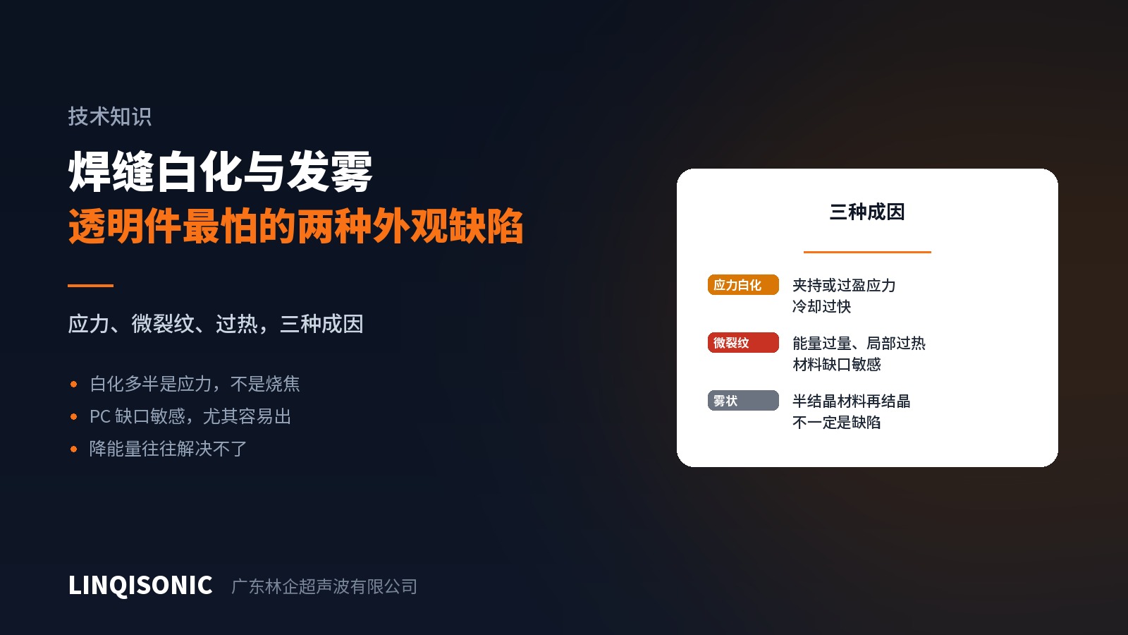
Whitening or haze around the joint stands out sharply on clear and light-coloured parts. The first assumption is usually "too much energy, it burned" — and after turning everything down, the weld is weak and the whitening is still there.
Because heat may not be the cause at all.
Three causes, three different directions
1. Stress whitening. When plastic is stretched or sheared beyond its elastic limit, microscopic voids open between molecular chains, scatter light, and appear white. The cause is mechanical, not thermal.
Common sources: over-tight fixturing, excessive joint interference, the edge of a horn impression, or part deflection under weld force. Notch-sensitive materials such as PC and PMMA are especially prone.
2. Micro-cracking from local overheating. Excessive or concentrated energy raises the temperature near the interface too far too quickly, and rapid cooling leaves a network of micro-cracks that also read as white. This is the case that genuinely is "burnt".
3. Re-crystallisation haze. In semi-crystalline resins (PP, PE, POM, nylon), the crystal structure after melting and re-solidifying differs from the original and clarity changes. This is not necessarily a defect — appearance changes while strength may be unaffected.
Telling them apart
Location. Whitening at the edge of a horn impression, at fixture contact points, or at part corners → most likely stress. In the middle of the joint, hard against the fused zone → more likely heat.
Timing. Present immediately → caused during welding. Appearing after storage or a temperature change → residual stress relaxing, meaning stress is locked into the part.
Try annealing. Stress whitening usually reduces or disappears after annealing below the softening point; micro-cracking does not. A reliable discriminator.
Treating each
Stress whitening — reduce clamping force, check fixture-to-part fit, reduce joint interference, enlarge the horn contact area to spread pressure, slow the approach, and extend hold so stress relaxes under force. Note that reducing weld energy achieves little here.
Thermal micro-cracking — reduce energy or time, reduce amplitude, check horn-to-part parallelism (misalignment concentrates energy locally), and check whether the director is too tall.
Re-crystallisation haze — hard to remove; it is a material characteristic. Where appearance matters, place the joint out of sight at the design stage or move to an amorphous resin.
One recommendation for clear parts
PC, PMMA and PETG carry high appearance expectations and happen to be notch-sensitive. Designing the joint onto a non-visible face is far more effective than adjusting parameters afterwards — and that decision belongs on the drawing.
Notch sensitivity by material and interference values by joint form are in the handbooks on the downloads page. Force control and approach speed by machine are on the ultrasonic welding machine pages.
Send photographs and resin grade to 1427498429@qq.com, or call +86 769 8202 9510 / +86 137 6001 0932.